Motor Board v0 - Breadboard
The precursor to Motor Board v1 - Itsy Bitsy Motor Board, this was built on a breadboard. It’s the exact same circuit as Motor Board v1 - Itsy Bitsy Motor Board.
components
-
breadboard
-
1x Adafruit ItsyBitsy M4 (https://www.adafruit.com/product/3800)
-
1x Adafruit DRV8833 (https://www.adafruit.com/product/3297)
-
2x Pololu Magnetic encoder with jst sh connector (https://www.pololu.com/product/4761)
-
some male / female socket headers
Schematic
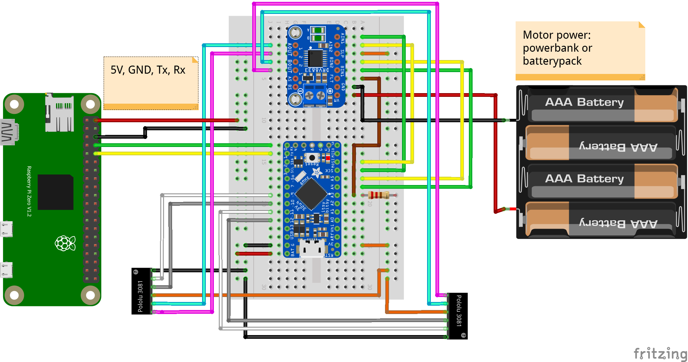
On the left, we have the Raspberry Pi Zero. Besides giving 5V (red) and GND (black) to the rest of the circuit, it communicates with the ItsyBitsy M4 via serial communication using the Rx/Tx pins.
The Pololu black rectangles at the bottom represent the 6-pin magnetic encoders which connect to the motors. They connect to the motor driving signals (cyan/magenta), inputs on the ItsyBitsy to read the encoder pulses (white/gray) and signal power (orange 3.3V / black GND).

The remaining wires on the right between the ItsyBitsy M4 and the DRV8833 chip (at the top) connect outputs of the ItsyBitsy M4 to the IN ports of the DRV8833 (yellow / green wires). The DRV8833 will output the same signals on its OUT ports, but with more power (cyan / magenta).
The battery box connects to GND / VM of the DRV8833 board, and is only used to power the motors. The ItsyBitsy is powered separately by the Raspberry Pi 5V/GND.
The optional brown wire and resistor are for reading the FLT (fault) output of the DRV8833. I never used it in practice to be honest. Also, in the schematic above, the right side of the resistor seems to be not connected to anything, it should go to 3.3V.
You can find the Fritzing schematic file here.
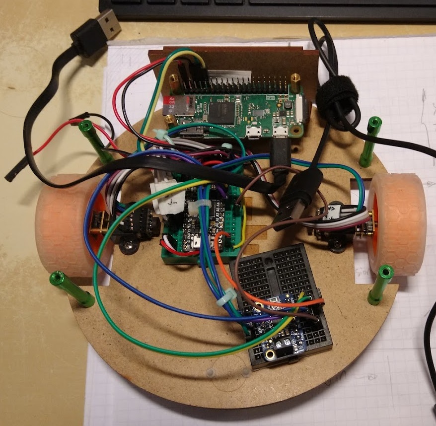
Spaghetti Mess
It’s doable using a breadboard, but as you can see it is a bit messy. You can get it tidier than the image below, but using a PCB makes it of course much more cleaner.
Code
See Motor Board Code