Captain Biscuit
Captain Biscuit is the name of a happy two-wheel differential drive robot.
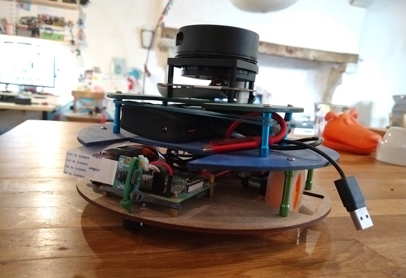
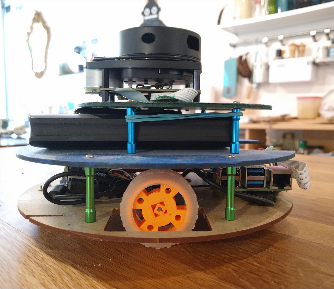
Hardware setup
Captain Biscuit has two computers on board:
The low-level driving is managed by Arduino code running on an ItsyBitsy M4 Express. It accepts commands over a serial UART interface to e.g. set the motor speed. More info in the itsybitsy-m4-motor repo! The ItsyBitsy M4 Express reads the wheel encoders and sends PWM signals to a DRV8833 chip to drive the motors. The wiring can be done on a breadboard, as explained in the itsybitsy-m4-motor repo. I also built a PCB to make it a bit less messy, the CAD of which is available in this repo (https://bitbucket.org/karelbraeckman/itsy-bitsy-motor-board/src/master/).
| update - I created a second, more powerful version of the motor driver board based on the cheaper and more common ESP32. It can run the same code. Should you replicate this build, it is advised to use this board instead. |
The high level stuff is managed using the nodejs code in this repository. It runs on a Raspberry PI which communicates with the motor board using the UART interface. To get a sense of the environment and not run into obstacles, the Raspberry PI is connected to the RPLIDAR A1, a budget (about 120€) 360deg laser range scanner.
The Code
The code in this repo runs on the real robot (on a Raspberry Pi). However, a small simulator is also included that can execute the same code, to make it easier to debug and test the code.
Usage
node run src/index.jsThe code will try to connect to the hardware (Lidar, motor driver board). If it fails, it will use a simulator alternative for the missing component.
The code also serves a web page at http://localhost:3000 where you can interact with the robot or the simulator. The interface shows a bunch of buttons. In simulation mode, press play/pause and drag the red circle somewhere to give a new target position for the robot.
Build the robot
Arduino code
The Arduino code is in the captain-biscuit-arduino folder. I used the platformio IDE to build it instead of the standard Arduino IDE.
The code exposes the command interface using the ItsyBitsyMotorBoard library and adds a few commands of its own.
Electronics
First build the motor driver board using the pcb or on a breadboard following the connections and components explained at https://bitbucket.org/karelbraeckman/itsybitsy-m4-motor/src/master/. It also explains which motors and encoders were used.
Connect the 5V, GND, RX and TX to a Raspberry PI. As the localization and mapping is very CPU intensive, a Raspberry PI 4 is advised.
| Motor Board | Raspberry |
|---|---|
5V |
5V |
GND |
GND |
RX |
TX |
TX |
RX |
Connect the RPLIDAR A1 via the usb cable to the Raspberry PI.
Connect a raspberry PI camera to the Raspberry PI using the camera cable connector.
The Raspberry PI 4 needs quite a lot of current to run, so connect a powerful powerbank to power it (via the USB-C connector). Preferably a model able to deliver 3 Amps or more of current at 5V.
Connect another powerbank or batteries to the motor power + and -. I used a micro usb connector and just used a small powerbank. The micro metal gear motors don’t draw that much current so this worked fine.